
A Practical Guide to Varistors
Voltage spikes can quietly damage electronic circuits, even when everything seems to be working fine. That’s where varistors come in. They sit in a circuit and stay out of the way until voltage rises beyond what’s expected. When that happens, they react fast and help limit the stress seen by other parts. In this guide, you’ll learn what a varistor is, how it behaves when voltage changes, the different types you might come across, and where it’s commonly used. By the end, you’ll have a clear picture of how varistors fit into real electronic designs.Catalog
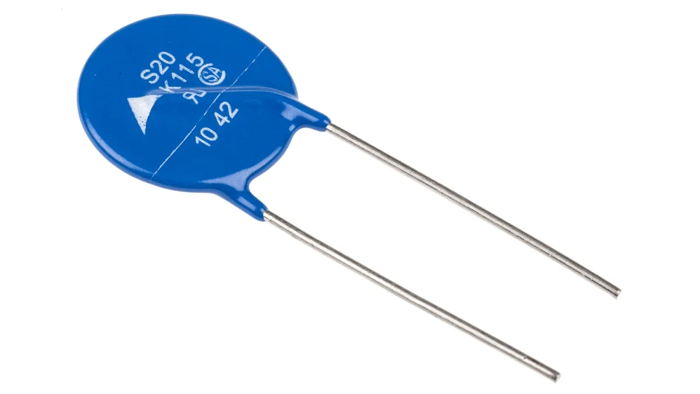
Figure 1. Disc-Type Varistor Component
What Is a Varistor?
A varistor is an electronic component whose resistance changes according to the voltage applied across it. The term comes from variable resistor, reflecting its voltage-dependent nature. Unlike fixed resistors, a varistor does not maintain a constant resistance during operation.
At normal voltage levels, a varistor exhibits very high resistance and allows only minimal current to pass. When the applied voltage exceeds a defined threshold, the resistance decreases rapidly. This response occurs inherently within the material and does not rely on external control, adjustment, or switching.
This voltage-sensitive behavior defines the fundamental identity of a varistor. Its electrical characteristics are nonlinear, meaning the relationship between voltage and resistance is not proportional. The device remains largely inactive during standard operation and changes state only when voltage rises beyond its intended range.
How a Varistor Works
A varistor changes its resistance based on the applied voltage. Under normal conditions, it remains at high resistance and does not affect circuit operation.
Voltage-Dependent Resistance Behavior
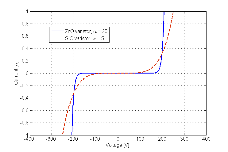
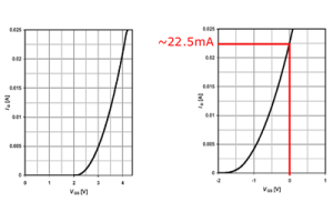
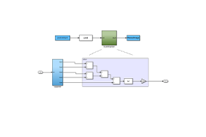
Figure 2. Varistor Current–Voltage Characteristics
A varistor operates based on a nonlinear relationship between voltage and current. At low and normal voltage levels, the device maintains very high resistance, which allows only a minimal amount of current to pass. In this region, changes in voltage produce little change in current, so the varistor remains largely inactive within the circuit.
As the applied voltage increases and approaches a defined threshold voltage, the electrical behavior begins to shift. Once this threshold is exceeded, the resistance of the varistor decreases sharply, and the current rises rapidly. This change does not occur gradually. Instead, it happens within a narrow voltage range, which is a defining characteristic of voltage-dependent resistors.
The sharpness of this transition reflects the degree of nonlinearity of the material used. Some varistors show a steeper rise in current for a small increase in voltage, while others respond in a more moderate way. This behavior is commonly expressed using a general current–voltage relationship written as I = k · V^α, where the exponent indicates how strongly the current responds to voltage changes. A higher value corresponds to a more abrupt transition.
This nonlinear resistance behavior allows the varistor to remain electrically unobtrusive during normal operation, while responding decisively when voltage rises beyond its intended range.
Response During a Voltage Surge
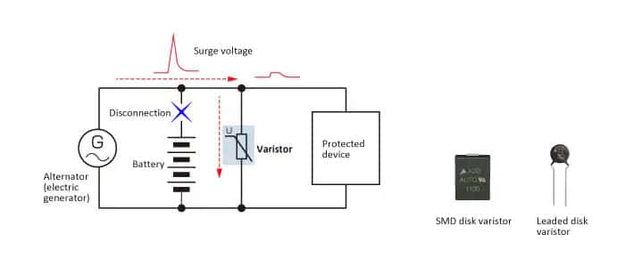
Figure 3. Varistor Operation During a Voltage Surge
When a sudden voltage spike occurs, the varistor responds automatically as the applied voltage exceeds its defined threshold. At this point, the device transitions from a high-resistance state to a low-resistance conductive state, allowing excess current to flow through it rather than continuing along the normal circuit path.
As current is redirected, the voltage across the connected circuit is limited to a lower level. This limiting action reduces the peak voltage experienced during the surge. The change in conduction occurs rapidly and lasts only for the duration of the voltage spike.
During this brief interval, part of the surge energy is absorbed by the varistor material and dissipated internally. Once the voltage returns to its normal range, the varistor exits the conductive state and returns to high resistance, effectively restoring its original electrical condition.
Types of Varistors
Varistors come in several types, each suited to different electrical conditions and applications.
Metal Oxide Varistors (MOVs)
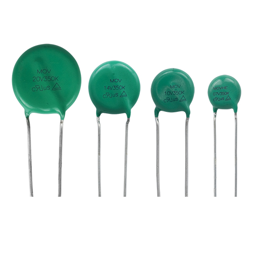
Figure 4. Metal Oxide Varistor (MOV) Types
Metal oxide varistors are the most widely used type in modern electronic systems. They are constructed from a ceramic material composed primarily of zinc oxide grains, which form a network of junctions within the device. This structure gives MOVs their strong nonlinear resistance behavior.
MOVs respond quickly when voltage exceeds a defined level and are capable of absorbing large amounts of surge energy. Because of this combination of fast response and high energy handling, they are commonly used for general-purpose surge protection. Typical applications include power lines, power supplies, household electronics, and commercial electrical equipment.
Silicon Carbide Varistors (SiC Varistors)
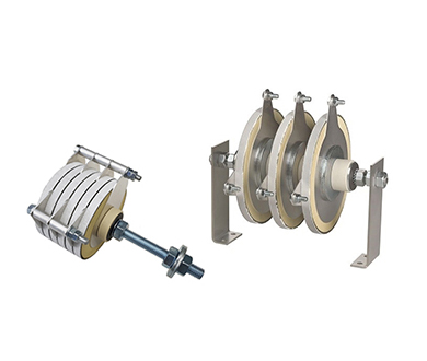
Figure 5. Silicon Carbide Varistors for High Power
Silicon carbide varistors are designed for high-voltage and high-power environments. They can tolerate strong electrical stress and are suitable for circuits exposed to large voltage variations. However, under normal operating voltage, these devices exhibit higher leakage current compared to other varistor types.
Due to this characteristic, silicon carbide varistors are less suitable for low-voltage or precision electronic circuits. They are more commonly found in industrial systems where higher standby current is acceptable and robust voltage handling is required.
Multilayer Varistors (MLVs)
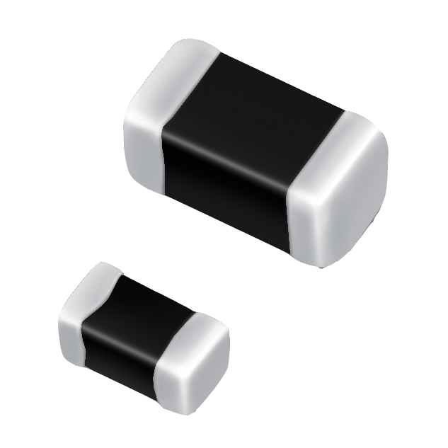
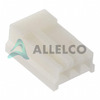
Figure 6. Multilayer Varistor Surface-Mount Packages
Multilayer varistors are compact devices designed primarily for surface-mount applications. They use multiple thin ceramic layers stacked together to achieve voltage-dependent resistance in a much smaller physical size than traditional disk-type varistors.
MLVs are best suited for low-energy transient protection. They are widely used in portable electronics, communication equipment, and densely populated circuit boards where space is limited. Their small size makes them practical for modern electronic designs that require localized protection.
Low-Capacitance Varistors
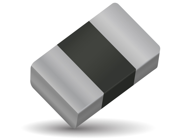
Figure 7. Low-Capacitance Varistor for Signal Lines
Low-capacitance varistors are optimized for use in signal and communication lines. These devices are designed to minimize capacitance so they do not interfere with signal quality. Low capacitance is important in circuits where high-speed signals, audio data, or digital communication must remain undistorted.
Because standard varistors can affect signal integrity, low-capacitance versions are commonly used in data interfaces, audio connections, and communication ports where maintaining signal clarity is critical.
High-Energy Varistors for Industrial Use

Figure 8. High-Energy Varistor for Industrial Protection
High-energy varistors are built to handle large surge currents and high pulse energy. These devices are physically larger and designed for demanding electrical environments. Their construction allows them to absorb strong transient events without immediate failure.
Such varistors are typically used in industrial power systems, heavy machinery, and AC mains protection. Their role is to provide robust protection in applications where electrical surges are frequent or particularly severe.
How to Choose the Right Varistor
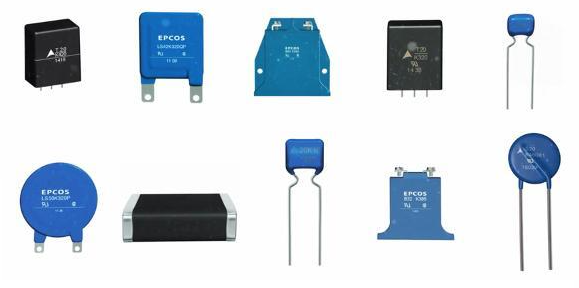
Figure 9. Common Varistor Package Variations
Selecting the right varistor is important because it directly affects how well a circuit is protected and how safely it operates. A poorly chosen varistor may fail to limit voltage properly or may degrade quickly under stress, reducing its protective value.
The selection process begins with understanding the normal operating voltage of the circuit. The varistor must be rated above this level so it remains inactive during normal operation. At the same time, its response level must be low enough to react when abnormal voltage conditions occur.
Another key factor is the expected surge conditions. Different circuits are exposed to different surge strengths, durations, and frequencies. Choosing a varistor with suitable energy and current handling capability ensures it can withstand these events without damage.
Physical and application constraints also matter. Space limitations, connection type, and whether the varistor is used on a power line or signal line all influence the choice. Careful selection helps balance effective protection, long-term reliability, and overall circuit safety.
Advantages and Limitations of Varistors
| Advantages | Limitations |
| Fast response to voltage transients | Degrades with repeated surge exposure |
| Simple and passive device operation | Limited lifespan under frequent surges |
| High surge current handling capability | Not suitable for long-duration overvoltage |
| Effective voltage clamping for short transients | Clamping voltage shifts downward over time |
| Wide range of voltage and energy ratings | Can fail in short-circuit mode |
| Easy to integrate into circuits | Requires proper coordination with fuses |
| Low cost compared to other protection devices | Generates heat during surge events |
| Available in many package sizes | Performance affected by temperature extremes |
| Suitable for AC and DC applications | Leakage current increases as device ages |
| High energy absorption in compact form | Not ideal for precision signal protection |
Common Applications of Varistors
Figure 10. Varistors Used in Power and Control Circuits
Varistors are widely used in electronic systems where protection against unexpected voltage spikes is required. One of the most common applications is in power supplies, where they help limit sudden voltage increases that could damage internal components. They are also a key element in surge protectors and power strips, providing protection for connected devices during transient events on the mains supply.
In consumer electronics, varistors are used to protect circuits in devices such as televisions, computers, chargers, and home appliances. These products are often connected directly to power lines, making them vulnerable to voltage disturbances that varistors are designed to handle.
Varistors are also found in industrial equipment, where electrical systems are exposed to higher power levels and more frequent switching events. In these environments, they help protect control circuits, motor drives, and power distribution systems from voltage stress.
In automotive systems, varistors are used to manage voltage spikes caused by inductive loads, such as motors and solenoids, and by fluctuations in the vehicle’s electrical system. Their ability to respond quickly makes them suitable for protecting sensitive electronic modules in modern vehicles.
Varistor Symbols and Circuit Placement
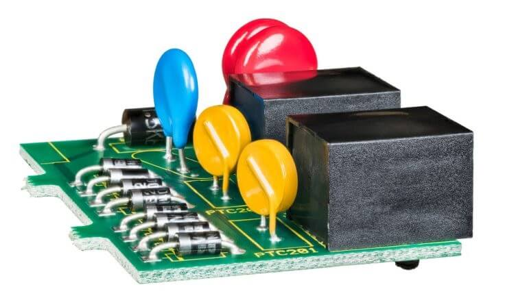
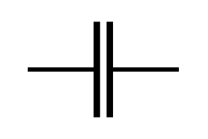
Figure 11. Varistor Circuit Symbol
In circuit diagrams, a varistor is shown using a resistor-based symbol that indicates its voltage-dependent resistance. This symbol distinguishes it from a fixed resistor and signals that the component responds to changes in voltage rather than current alone.
Varistors are commonly placed directly across the lines that require protection. In power circuits, this usually means a connection between supply lines or between a supply line and ground. In signal circuits, the device is typically connected between the signal line and ground.
Correct placement ensures that the varistor can respond promptly to excessive voltage at the point where it appears. Locating the component close to the protected line helps limit the voltage seen by the circuit during transient events.
Conclusion
Varistors play a quiet but important role in protecting electronic circuits from sudden voltage changes. You’ve seen how their resistance changes with voltage and why that behavior makes them useful for handling spikes. Different varistor types exist to match different voltage levels, energy demands, and circuit constraints. Choosing the right one helps improve reliability and reduce the risk of damage. When placed correctly, a varistor can absorb stress that would otherwise reach sensitive parts. Understanding how they work makes it easier for you to use them confidently in everyday electronics.
Meistä
ALLELCO LIMITED
Lue lisää
Nopea kysely
Lähetä kysely, vastaamme heti.
Usein Kysytyt Kysymykset [FAQ]
1. What does a varistor do in a circuit?
A varistor helps limit excessive voltage by changing its resistance when voltage rises beyond a set level.
2. Is a varistor active during normal operation?
No, it remains at high resistance and has little effect on the circuit under normal voltage conditions.
3. Are varistors used in both AC and DC circuits?
Yes, varistors can be used in both AC and DC applications when properly rated.
4. Do varistors wear out over time?
Yes, repeated exposure to voltage surges can gradually reduce their performance.
5. Where should a varistor be placed in a circuit?
It is usually placed across the line or between a line and ground where voltage spikes are expected.
4k7-vastuksen selitys: arvo, värikoodi, tyypit ja sovellukset
26.01.2026
Tyhjennystilan MOSFET: tyypit, ominaisuudet, painotus ja sovellukset
26.01.2026
Suositut viestit
-
COMPLECT -ohjeet Tietokoneet: Kuinka ne muuttivat tietojenkäsittelyä?
11.06.8000 148369
-

USB-C-pinout ja ominaisuudet
11.06.2000 131099
-
Xilinx Unified Simulation Primitive -sovelluksen käyttäminen: Kattava opas FPGA: n suunnitteluun ja simulointiin
11.06.1600 111849
-

Virtalähteen jännitteet elektroniikassa: VCC:n, VDD:n, VEE:n, VSS:n ja GND:n merkitys
11.06.0400 94106
-

RJ45 Connector Guide: Pinout, johdotus, kaapelityypit ja käyttö
01.01.1970 93481
-

Lopullinen opas johdon värikoodiin nykyaikaisissa sähköjärjestelmissä
Tapa, jolla sähköjärjestelmämme käyttävät värejä, ei ole vain ulkonäölle.Jokainen lankaväri osoittaa nyt tietyn toiminnon, mikä helpottaa sähkökomponenttien tunnistamista ja käsittelyä oikein asenn...01.01.1970 76627
-

Laatu (Q) tekijä: Yhtälöt ja sovellukset
Laatukerroin tai 'Q' on tärkeä tarkistettaessa, kuinka hyvin induktorit ja resonaattorit toimivat elektronisissa järjestelmissä, jotka käyttävät radiotaajuuksia (RF).'Q' mittaa kuinka hyvin piiri m...01.01.1970 74628
-
Puhdistusventtiilin opas: Toiminta, oireet, testaus ja korvaava moottorin optimaalinen suorituskyky
Puhdistusventtiili on keskeinen osa auton järjestelmää, joka auttaa pitämään ilman puhtaana hallitsemalla polttoainehöyryjä ennen kuin ne voivat paeta ilmakehään.Tämä ei vain auta ympäristöä vähent...01.01.1970 68566
-
Kondensaattorien ja niiden symbolien ymmärtäminen piirikaavioissa
Kondensaattorit ovat pieniä osia, joita käytetään melkein kaikissa elektronisissa laitteissa.Ne säilyttävät ja vapauttavat sähköenergiaa, ja niitä löytyy esimerkiksi virtalähteistä, radioista ja pi...11.06.2000 58355
-

A23 -akun tekniset tiedot ja yhteensopivuus
A23-akku on pieni, sylinterimainen akku, jolla on korkea jännite.Kutsutaan myös 23a, 23ae tai MN21, se toimii 12 voltilla ja paljon korkeampi kuin AA- tai AAA -akut.Sen erityinen muotoilu ...01.01.1970 57907
Kuuma osanumero
-

AT90S8535-8JI
Microchip Technology
IC MCU 8BIT 8KB FLASH 44PLCC
12103C226KAT2A
AVX Corporation
CAP CER 22UF 25V X7R 1210
OPA234P
Texas Instruments
IC OPAMP GP 350KHZ SGL LP 8DIP
LTC3568IDD#TRPBF
Analog Devices Inc.
IC REG BUCK ADJ 1.8A 10DFN
DTC015EMT2L
Rohm Semiconductor
TRANS PREBIAS NPN 50V VMT3
FAN4802NY
onsemi
IC PFC CTR AVER CURR 64KHZ 16DIP
NCS4-232+
Mini-Circuits
1:4 LTCC TRANSFORMER, 1600 - 230
A6266KLPTR-T
Allegro MicroSystems
IC LED DRVR CTRL PWM 1A 16ETSSOP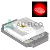
SML-P12UTT86
Rohm Semiconductor
LED RED CLEAR 1006 SMD
LB1930MC-AH
onsemi
IC MOTOR DRVR 2.2V-10.8V 10SOIC
MIC3809BMM
Microchip Technology
IC REG CTRLR MULT TOPOLOGY 8MSOP
MMBD914LT3
onsemi
DIODE SWITCHING HS 100V SOT-23
IRFI540NPBF
Infineon Technologies
MOSFET N-CH 100V 20A TO220AB FP
FQA34N25
onsemi
MOSFET N-CH 250V 34A TO3P
MAX14809ETK+T
Analog Devices Inc./Maxim Integrated
IC MUX DUAL HV 68TQFN
GRM1886P1H1R4CZ01D
Murata Electronics
CAP CER 1.4PF 50V P2H 0603
ISL88003IH31Z-T
Renesas Electronics America Inc
IC SUPERVISOR 1 CHANNEL SOT23-3
LT3045HDD#PBF
Analog Devices Inc.
IC REG LIN POS PROG 500MA 10DFN -

BQ24738RGRT
Texas Instruments
PROTOTYPE
DP83TC811SWRNDRQ1
Texas Instruments
IC TRANSCEIVER 2/2 36VQFN
GRM188R61A226ME15D
Murata Electronics
CAP CER 22UF 10V X5R 0603
R5F212B8SNFA#V2
Renesas Electronics America Inc
IC MCU 16BIT 64KB FLASH 64LQFP
ISL8026AIRTAJZ
Renesas Electronics America Inc
IC REG BUCK ADJUSTABLE 6A 16TQFN
TSX712IYDT
STMicroelectronics
IC CMOS 2 CIRCUIT 8SOIC
MMBD6050LT1G
onsemi
DIODE GEN PURP 70V 200MA SOT23-3
VI-JNP-EW
Vicor Corporation
DC DC CONVERTER 13.8V 100W
TLC551CD
Texas Instruments
IC OSC SGL TIMER 1.8MHZ 8-SOIC
STM795SM6F
STMicroelectronics
IC SUPERVISOR 1 CHANNEL 8SO
HSMS-280K-BLKG
Broadcom Limited
RF DIODE SCHOTTKY 70V SOT363
A54SX16P-VQ100
Microchip Technology
IC FPGA 81 I/O 100VQFP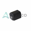
P1812-562K
API Delevan Inc.
FIXED IND 5.6UH 650MA 437MOHM SM
MB90553BPMC-G-341-JNE1
Infineon Technologies
IC MCU 16BIT 128KB MROM 100LQFP
MAX313LEUE+
Analog Devices Inc./Maxim Integrated
IC SW SPST-NOX4 10OHM 16TSSOP
SFH6719
Vishay Semiconductor Opto Division
OPTOISO 5.3KV TRI-STATE 8DIP
RT9011-CMGJ6
Richtek USA Inc.
IC REG LINEAR 1.2V/2.8V TSOT23-6
VI-2T3-IV
Vicor Corporation
DC DC CONVERTER 24V 150W -
171822-3
TE Connectivity AMP Connectors
CONN RCPT HSG 3POS 2.50MM
MMB02070C1500FB200
Vishay Beyschlag/Draloric/BC Components
RES SMD 150 OHM 1% 1W 0207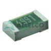
TNPW060320K0BEEN
Vishay Dale
RES 20K OHM 0.1% 1/10W 0603
AOWF14N50
Alpha & Omega Semiconductor Inc.
MOSFET N-CH 500V 14A TO262F
1N3087R
Vishay General Semiconductor - Diodes Division
DIODE GEN PURP 300V 150A DO205AC
FRDM-KL05Z
NXP USA Inc.
FREEDOM KL04/KL05 DEV EVAL BRD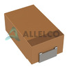
TPSD227K006R0100
KYOCERA AVX
CAP TANT 220UF 10% 6.3V 2917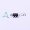
OPA335AIDBVR
Texas Instruments
IC OPAMP ZER-DRIFT 1CIRC SOT23-5
MAX8915AIWW+T
Analog Devices Inc./Maxim Integrated
IC CCD CLOCK DRIVER WLP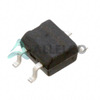
CDBHM140L-HF
Comchip Technology
BRIDGE RECT 1PHASE 40V 1A MBS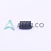
MBRA140T3G
onsemi
DIODE SCHOTTKY 40V 1A SMA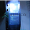
AD9203ARU
Analog Devices Inc.
IC ADC 10BIT PIPELINED 28TSSOP
AD8541AR
Analog Devices Inc.
IC OPAMP GP R-R CMOS 1MHZ 8SOIC
LQP15MN6N8B02D
Murata Electronics
FIXED IND 6.8NH 130MA 900MOHM SM
RC0805FR-074K99L
YAGEO
RES 4.99K OHM 1% 1/8W 0805
R3111H421A-T1-FE
Nisshinbo Micro Devices Inc.
IC SUPERVISOR 1 CHANNEL SOT89-3
XC6216C201PR-G
Torex Semiconductor Ltd
IC REG LINEAR 2V 100MA SOT89-5
MAX8784ETL+
Analog Devices Inc./Maxim Integrated
IC REG STP UP W/AMP 40-TQFN